
AI Use Disclaimer
- I have used AI throughout the design process
- Usage went something like this:
- I want to design a PCB to do whole HVAC performance analysis
- Refine parts selection for that based on availability, practicality and personal goals
- Personally realize two PCB design made more sense
- Continue down path with that new understanding and focusing on re-use
- Takeaways:
- AI does sometimes hallucinate
- AI does not have accurate pricing/availability in many cases (stale data? data accessibility?)
- It’s nearly impossible to keep my mental model in sync with AI so drifts occur where the model was misaligned…this was frequent and I usually just ask guiding questions until things get too far off track
- I tried to use AI as a fast research tool, that I then followed up with web searches to back up the models suggestions, fill-in my understand, or correct it where necessary
- How much is straight up AI?
- Sensor selection 50%
- Useful, but sometimes misguided, highly tailored based on availability and practicality
- Chip selection 75%
- Good starting point, sometimes I find my own parts after I understand the HW purpose behind the chip inclusion
- System Design 10%
- Most of the system design came from me or my guidance based on the things I knew I want measured
Alpha Revision
This is an alpha revision design, please take this into account when reviewing or using this product.
Overview
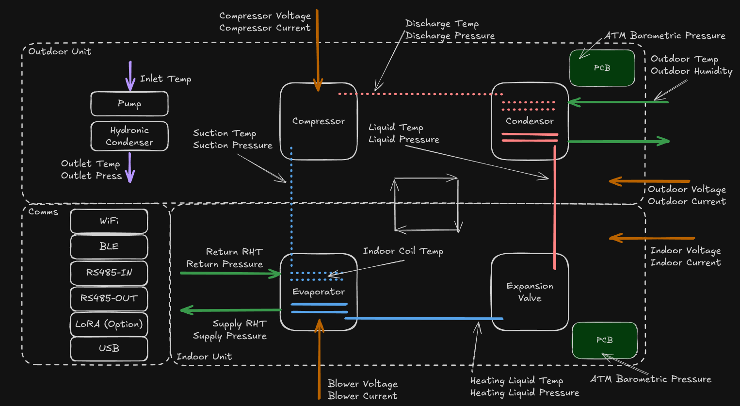
The goal of this PCB is to prototype some of the most common sensor types, power generation, communication protocols and non-secondary MCU module, either first party module or chip-down.
System Diagram
Circuit Design
Subsystems:
- Microcontroller
- Power
- Current Measurement
- Phase Detection
- Temperature Sensing
- Pressure Sensing
- 24VAC Presence Detection
- Humidity & Temperature Sensing
- Wireless Interfaces
- Wired Interfaces
Microcontroller
- Use ESP32-S3
- I have changed from the ESP32-C3 due to IO needs
- Integrated Wi-Fi
- Integrated BLE
- Large RAM and ROM
- Good IO compliment and versatile IO Mux System
Power
- Utilize 24VAC input from the present system this is installed in
- Convert to 12VDC and 5VDC using Buck Converters
- …Since this board is no longer being used for control and will now be used only for sensing, I’m not sure 12VDC is needed, I might drop this?
- Convert to 3.3VDC using and LDO
Current Measurement
- Target using a Current Transformer (CT) via TRS connector
- Leaning towards current output, requiring a burden resistor on PCB
- …This was my original thinking, however, I have since realized that with the varieties of ways a unit can be powered this might be very finicky to set up, yet is critical for the COP calculation
- Move towards using a Modbus based Power Analyzer
- This allows to adapt to the need of the customer
- It requires a little more setup and know-how, but will probably achieve better results for comparable cost
Phase Detection
- Rely on 24VAC presence detection
- Pass the Current Transformer signal to the same circuit
- Compare the delta time between signals, which will indicate phase shift for power analysis
- …this is no longer needed if we are using a 3rd party power analyzer
Temperature Sensing
- Most commonly people use a 10KOhm NTC Thermistor
- There are some PTC sensors out there that have better linearity, but they are uncommon
- Relying on DS18B20 saves IO, improves accuracy, reduces circuit complexity, although it adds sensor cost
Pressure Sensing
- Design for a 5V ratiometric pressure sensor
24VAC Presence Detection
- Opto-isolator with load resistor for 24VAC detection
Humidity and Temperature Sensing
- Rely on I2C sensors as they are common
Wireless Interfaces
- Wi-Fi is built into the ESP32 chip
- BLE is built into the ESP32 chip
- Add 915MHz LoRA chip onboard
- Add NFC Chip / Antenna onboard
- I might not do this as it adds a lot complexity to the PCB design and BLE is nearly as good/can do proximity based stuff. Maybe a later revision?
Wired Interfaces
- RS-485 chip interface
- Modbus
- BACnet
- USB Port
Interface Assignment
| DNP | IO / Interface | Indoor Function | Outdoor Function | Notes |
|---|---|---|---|---|
| DNP | ADS1115[0] | Return Plenum Static Pressure | Suction Pressure | |
| ADS1115[1] | Supply Plenum Static Pressure | Discharge Pressure | ||
| ADS1115[2] | Heating Liquid Pressure | Liquid Pressure | ||
| ADS1115[3] | Hydronic Pressure | |||
| I2C0[0x48] | ADS1115 | ADS1115 | ||
| I2C0[0x44] | SHT85/SHT40 - Return T/RH | SHT85 - OAT T/RH | Shared address? Consider power enable? | |
| I2C1[0x44] | SHT85/SHT40 - Supply T/RH | N/A | Search google for “Probe” | |
| I2C1[0x76] | ATM Barometric Pressure | |||
| DNP | I2C1[0x55] / GPIO[FD] / GPIO[RST] | NFC NTAG I2C+ (NT3H2111W0FT1X) | NFC NTAG I2C+ (NT3H2111W0FT1X) | LED on FD |
| GPIO[TS_DATA] | DS18B20 | DS18B20 | ||
| DS18B20[0] | Evap Surface Temp | Suction | ||
| DS18B20[1] | Backup Return Temp | Discharge | ||
| DS18B20[2] | Backup Supply Temp | Liquid Line | ||
| SPI / GPIO[RXEN] / GPIO[BUSY] / GPIO[TXEN] / GPIO[RST] | 915MHz Radio (RA-01SH) | 915MHz Radio (RA-01SH) | LED on BUSY | |
| USB[DP] / USB[DM] / VBUS (optional) | USB | USB | Consider a 5V bypass to power board from USB LED on VBUS | |
| GPIO[LED_DATA] | WS2812 LEDs | WS2812 LEDs | ||
| WS2812[00] | Status LED | Status LED | ||
| WS2812[01] | WiFi LED | WiFi LED | ||
| WS2812[02] | BLE LED | BLE LED | ||
| WS2812[03] | LoRA LED | LoRA LED | ||
| WS2812[04] | NFC LED | NFC LED | ||
| WS2812[05] | Indoor Current LED | Outdoor Current LED | ||
| WS2812[06] | Return Pressure LED | Suction Pressure LED | ||
| WS2812[07] | Supply Pressure LED | Discharge Pressure LED | ||
| WS2812[08] | ATM Pressure LED | Liquid Pressure LED | ||
| WS2812[09] | Evap Surface Temp LED | Suction LED | ||
| WS2812[10] | Backup Return Temp LED | Discharge LED | ||
| WS2812[11] | Backup Supply Temp LED | Liquid Line LED | ||
| WS2812[12] | T/RH Return | T/RH OAT | ||
| WS2812[13] | T/RH Supply | N/A | ||
| DNP | SPI | Flash | Flash | ESP32 has enough flash? |
| UART1 (RS-485_OUT) / GPIO[RS485_OUT_DE] | Power - Unit | Power - Unit | Modbus | |
| UART1 (RS-485_OUT) / GPIO[RS485_OUT_DE] | Power - Fan | Power - Compressor | Modbus | |
| UART1 (RS-485_OUT) / GPIO[RS485_OUT_DE] | Power - Fan | Modbus | ||
| UART0 (RS-485_IN) / GPIO[RS485_IN_DE] | Modbus In | BACnet / Modbus In | ||
| GPIO[Button] | Multi-use Button | |||
| GPIO[Y1] | TSTAT_Y1 | |||
| GPIO[Y2] | ||||
| GPIO[W1] | ||||
| GPIO[W2] | ||||
| GPIO[G] | ||||
| GPIO[O/B] | ||||
| GPIO[AUX] |
MCU Utilization
Option 1: I2C Shared
| Type | Count | Usage |
|---|---|---|
| GPIO | 15 | RST, BUSY, TX_EN, RX_EN, LED_DATA, TS_DATA, RS485_IN_DE, RS485_OUT_DE, Button, Y1, Y2, W1, W2, G, O/B, AUX, RS485_IN_DE |
| SPI | 1 | LoRA / External |
| I2C | 2 | 1: SHT40, ADS1115; 2: SHT40, Headers |
| USB | 1 | USB Debug / Programming |
| UART | 2 | Modbus In (BACnet?), Modbus Out |
I2C Option
Based on I2C alignment and availability, we might need to use one I2C with a select line to swap power for commonly addressed sensors
NFC Option
NFC might not be feasible to add, time and I/O
Interface Cost Breakdown
Indoor
| Interface | Expensive Components | Connector | Sensor | Other |
|---|---|---|---|---|
| RH/T Return | $0.05 | $4 | ||
| RH/T Supply | $0.05 | $4 | ||
| Evap Surface Temp | $0.50 | $2.50 | ||
| Heating Liquid Temp | $0.50 | $2.50 | ||
| Supply Pressure | $0.50 | [50?) | ||
| Return Pressure | $0.50 | [50?) | ||
| Heating Liquid Pressure | $0.50 | $50 | ||
| Spare Pressure | ||||
| Barometric Pressure | $3.30 | |||
| ESP32-S3-WROOM-1U | $5.66 | |||
| LoRA | $10 | $15 | ||
| Breakout Connector | $0.50 | |||
| Power Circuit | ~$15 | |||
| ADS1115 | $5.30 | |||
| Power Analyzer | $20x2 | |||
| Wiring | $10 | |||
| PCB | $5 |
Really rough estimate for indoor board is ~
Outdoor
| Interface | Expensive Components | Connector | Sensor | Other |
|---|---|---|---|---|
| RH/T OAT | $0.05 | $4 | ||
| Discharge Temp | $0.50 | $2.50 | ||
| Suction Temp | $0.50 | $2.50 | ||
| Liquid Temp | $0.50 | $2.50 | ||
| Hydronic Inlet Temp | $0.50 | $2.50 | ||
| Hydronic Outlet Temp | $0.50 | $2.50 | ||
| Discharge Pressure | $0.50 | $50 | ||
| Suction Pressure | $0.50 | $50 | ||
| Liquid Pressure | $0.50 | $50 | ||
| Hydronic Pressure | $0.50 | $50 Placeholder | ||
| Barometric Pressure | $3.30 | |||
| ESP32-S3-WROOM-1U | $5.66 | |||
| LoRA | $10 | $15 | ||
| Breakout Connector | $0.50 | |||
| Power Circuit | ~$15 | |||
| ADS1115 | $5.30 | |||
| Power Analyzer | $20x2 | |||
| Wiring | $10 | |||
| PCB | $5 |
ESP32-S3 Pin Assignment
ESP32-C3-MINI-1(U) Datasheet ESP32-C6-WROOM Datasheet ESP32-S3-WROOM Datasheet
| Name | No. | Edge | Type | Function | Interface |
|---|---|---|---|---|---|
| GND | 1 | L | Power | Ground | |
| 3V3 | 2 | L | Power | Supply | |
| EN | 3 | L | Enable | ENABLE | Button |
| IO4 | 4 | L | I/O | I2C0_SDA | SHT40 bus 0 |
| IO5 | 5 | L | I/O | I2C0_SCL | SHT40 bus 0 |
| IO6 | 6 | L | I/O | I2C1_SDA | SHT40 bus 1 |
| IO7 | 7 | L | Output | LORA_RST | LoRa |
| IO15 | 8 | L | Input | LORA_BUSY | LoRa |
| IO16 | 9 | L | Output | LORA_TXEN | LoRa |
| IO17 | 10 | L | Output | LORA_RXEN | LoRa |
| IO18 | 11 | L | I/O | I2C1_SCL | SHT40 bus 1 |
| IO8 | 12 | L | Output | LED_DATA | WS2812s |
| IO19 | 13 | L | I/O | USB_DM | USB |
| IO20 | 14 | L | I/O | USB_DP | USB |
| IO3 | 15 | B | I/O | BREAKOUT0 | |
| IO46 | 16 | B | I/O | BREAKOUT1 | |
| IO9 | 17 | B | Output | TS_DATA | DS18B20s |
| IO10 | 18 | B | Output | LORA_CS | LoRa |
| IO11 | 19 | B | Input | FSPIQ | LoRa / Breakout |
| IO12 | 20 | B | Output | FSPICLK | LoRa / Breakout |
| IO13 | 21 | B | Output | FSPID | LoRa / Breakout |
| IO14 | 22 | B | Output | BRK_CS | Breakout |
| IO21 | 23 | B | Output | RS485_TX | Modbus |
| IO47 | 24 | B | I/O | BREAKOUT2 | |
| IO48 | 25 | B | Input | RS485_RX | Modbus |
| IO45 | 26 | B | I/O | BREAKOUT3 | |
| IO0 | 27 | R | Input | BOOT | Button |
| IO35 | 28 | R | Output | RS485_DE | Modbus |
| IO36 | 29 | R | Input | BUTTON | Button |
| IO37 | 30 | R | Input | TSTAT_Y1 | Thermostat |
| IO38 | 31 | R | Input | TSTAT_Y2 | Thermostat |
| IO39 | 32 | R | Input | TSTAT_W1 | Thermostat |
| IO40 | 33 | R | Input | TSTAT_W2 | Thermostat |
| IO41 | 34 | R | Input | TSTAT_G | Thermostat |
| IO42 | 35 | R | Input | TSTAT_OB | Thermostat |
| RXD0 | 36 | R | Input | RS485_IN_RX | Optional Log |
| TXD0 | 37 | R | Output | RS485_IN_TX | Optional Log |
| IO2 | 38 | R | Output | RS485_IN_DE | |
| IO1 | 39 | R | Input | TSTAT_AUX1 | Thermostat |
| GND | 40 | R | Power | Ground | |
| EPAD | 41 | R | EPAD | EPAD |
External Header
| Pin | Function | Function | Pin |
|---|---|---|---|
| 0 | 12V | 12V | 1 |
| 2 | PGND | PGND | 3 |
| 4 | 5V | BREAKOUT0 | 5 |
| 6 | 3V3 | BREAKOUT1 | 7 |
| 8 | GND | BREAKOUT2 | 9 |
| 10 | FSPIQ | BREAKOUT3 | 11 |
| 12 | FSPICLK | BREAKOUT4 | 13 |
| 14 | FSPID | BRK_CS | 15 |