Overview
- This board is designed as a daisy chain sensor PCB that takes in 4 wires and forwards that onto the next of this same PCB
- 5V to power the sensor and LED
- 1-Wire Data for parallel temperature measurement (DS18B20)
- LED Data for standard WS2812 8-bit 3 color protocol
- The LED should be used in accordance with the temperature sensor to provide interesting information locally to the sensor
Schematic
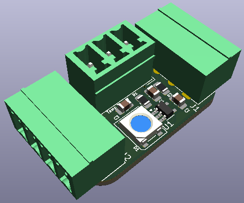
3D Model
Lessons Learned
- Having the pull-up resistors on all the DS18B20s will probably cause issues
- In the actual boards I will need a single pull-up on the host board and none on the daisy chained boards
Active Components
U1 - 74AHCT1G125GV
References
Purpose
This chip is used to ensure a crisp 5V signal to the LEDs as it is forwarded along the data bus. Also ensures that even if 3.3V is used for switching directly, it will pull up to 5V, although this might not be necessary.
Benefits
- Simplicity and ease of use, guaranteed performance for a part that is known to function in the application required.
- There isn’t any math that needs to occur to set up the circuit and the signals are actively driven which can give a better switched signal integrity.
- Faster switching speeds possible
Downsides
- Higher cost
Justification
Mostly what is noted above in the benefits, this is another area where I have used switches in previous applications and I was curious of using an alternate solution. Cost for this choice vs individual components is 0.03), which is a decent amount multiplier, but this is also a low volume part.
Alternatives / Future
Alternative to this chip would be using the 2N7002 or BSS138 plus necessary resistors implementing the switching circuit manually. This will also take up marginally more space on the PCB.
RGB LED - WS2812B
References
Purpose
RGB LEDs that allow for complex interaction with the user for:
- temperature sensor status
Benefits
- 1-wire & daisy chain LED control
- RGB LED for full spectrum color & Dimmable brightness
- Small package and decent cost for the value gained
Downsides
- Higher cost (although this is difficult to quantify compared to an individual LED of such lower value…less features, more IO needed)
- Requires 5V power to operate
- Requires baking before use, adds cost to PCB (there don’t seem to be any RGB LED that does not…typically MSL 5+)
Justification
Using a 1-wire LED will reduce the IO that is utilized by the Microcontroller allowing limited IO to go further. Daisy chaining supports this benefit further. There is some cost by needing 5V, but this should be present on HVAC PCB anyway for some sensing circuitry that requires it (pressures). Having an RGB and variable brightness LED also allows for complex expression of information.
Alternatives / Future
It is feasible to use individual LEDs but this severely limits expressiveness and adds a lot of IO needs. Regarding value I feel like you can’t beat an RGB LED. There are a lot of different packages so the only main change I would see here is, which package is optimal for a given design.
Brownie Points
A future design that has molded case + light guides to really utilize these LEDs to their fullest!
Temperature Sensors - DS18B20
References
Purpose
This part is the temperature sensor I have designed for. Any part that uses 3.3V for 1-wire control and utilizes 3.3V or 5V power are supported (although I’m not sure how many there are).
Benefits
- 1-wire, daisy chain control line
- Can be powered parasitically over the Data Line, requiring only 2 wires total (Data/GND) (requires pulling the data directly to VDD during conversion)
- Variable resolution 9-12 bits (adjusting conversion time & accuracy)
- ±0.5°C Accuracy from -10°C to +85°C
- No conversion necessary (Digital)
- No need for calibration
Downsides
- Higher cost compared to a standard thermistor
- Less tried and tested than a standard thermistor
- You cannot measure the temperature sensor directly to determine temperature
- Requires an addressing procedure to set up the sensor correctly
Justification
Similar to the LED, having a 1-wire setup can be advantageous. The limited IO on a MCU is used to better advantage with a 1-wire sensor, you can have many temperature sensors with 1 GPIO used. The accuracy and lack of calibration is also a nice bonus. It does have a higher cost, but I don’t think they would need to be replaced often. One other nice thing is that accuracy is isolated from external conditions. Since the sensing occurs right at the probe tip and digital past that, noise, conversion error is reduced.
Alternatives / Future
Standard NTC thermistor is always an option, this requires 1 Analog circuit per sensor and accuracy might be harder to guarantee. There are some newer Silicon based PTC thermistors that look interesting like the TMP61, or the TMP35. The TMP61 is a resistive component and more accurate, but unlike standard NTC thermistors or traditional PTC thermistors, is linear in it’s operating range. The TMP35 produces a voltage directly, but has lower accuracy than the TMP61.
BOM Table
CLICK HERE to enter reader mode to view this table
| Designator | Footprint | Quantity | Designation |
|---|---|---|---|
| C1 | C_0805_2012Metric_Pad1.18x1.45mm_HandSolder | 1 | 100uF |
| C2, C3 | C_0805_2012Metric_Pad1.18x1.45mm_HandSolder | 2 | 100nF |
| D1 | LED_WS2812B_PLCC4_5.0x5.0mm_P3.2mm | 1 | WS2812B |
| J1 | PhoenixContact_MC_1,5_4-G-3.81_1x04_P3.81mm_Horizontal | 1 | In |
| J2 | PhoenixContact_MC_1,5_4-G-3.81_1x04_P3.81mm_Horizontal | 1 | Out |
| J3 | PhoenixContact_MCV_1,5_3-G-3.81_1x03_P3.81mm_Vertical | 1 | Temp Sensor |
| R1 | R_0805_2012Metric_Pad1.20x1.40mm_HandSolder | 1 | 4.7k |
| R2, R3 | R_0805_2012Metric_Pad1.20x1.40mm_HandSolder | 2 | 33 |
| U1 | SC-74A-5_1.55x2.9mm_P0.95mm | 1 | 74AHC1G125 |